A compilation of practical explanations about
ANSI/VITA 57.1-2008 (R2010), FPGA Mezzanine Card (FMC) Standard
1. What form factors are specified by ANSI/VITA-57.1?
2. What types of connectors can be used?
3. What’s the difference between Molex and Samtec FMC connectors?
4. What EEPROM can be used for FRU information storage?
5. What is the pinout of the FMC connector?
1. What form factors are specified by ANSI/VITA-57.1?
Firstly, FMC modules are categorized by their width. Single width (69 mm) and double width (139 mm) mezzanine modules are specified. Secondly, they are divided in subtypes according to their cooling layout (air cooled or conduction cooled), mounting style (commercial grade or ruggedized) and module regions (optional region 1 for front panel I/O, region 2 for components, and optional region 3 for rear extension). Not all combinations are possible, a list of suitable form factors is given below.
| Width | Mounting | Cooling | Regions | Dimensions (L x W) | Drawings |
|---|---|---|---|---|---|
| Single | Commercial grade | Air cooled | 2 | 71.3 mm x 69.0 mm | mechanical layout 3D PCB image |
| Single | Commercial grade | Air cooled | 1, 2 | 76.5 mm x 69.0 mm | mechanical layout 3D PCB image |
| Single | Commercial grade | Air cooled | 2, 3 | 78.8 mm x 69.0 mm | mechanical layout 3D PCB image |
| Single | Commercial grade | Air cooled | 1, 2, 3 | 84.0 mm x 69.0 mm | mechanical layout 3D PCB image |
| Single | Ruggedized | Conduction cooled | 2, 3 | 78.8 mm x 69.0 mm | mechanical layout 3D PCB image |
| Single | Ruggedized | Conduction cooled | 1, 2, 3 | 84.0 mm x 69.0 mm | mechanical layout 3D PCB image |
| Double | … | … | … | … mm x 139.0 mm | coming soon |
2. What types of connectors can be used?
The FMC standard specifies a low-pin count (LPC) connector with 160 pins or high-pin count (HPC) connector with 400 pins. An LPC connector on mezzanine card side also fits into an HPC connector on baseboard side. Electrical signals are also compatible, as the LPC pinout is a reduced variant of the HPC pinout. At the moment, there are two major manufacturers for the connectors on baseboard (female) and mezzanine card side (male), Samtec (Samtec FMC connectors) and Molex (Molex FMC connectors). The variants are listed in the table below.
The parts marked in bold are most commonly used in ANSI/VITA 57.1 FMC systems.
| ANSI/VITA-57 FMC connector | Samtec FMC connector | Molex FMC connector | Description | Mated stack height |
|---|---|---|---|---|
| CC-LPC-10 | ASP-134603-01 | 45971-4305 | female, baseboard side, Low-pin count (LPC), 160 I/O, tin-lead | |
| CC-LPC-10L | ASP-127796-01 | 45971-4307 | female, baseboard side, Low-pin count (LPC), 160 I/O, tin-lead | |
| CC-HPC-10 | ASP-134486-01 | 45971-4315 | female, baseboard side, High-pin count (HPC), 400 I/O, lead-free | |
| CC-HPC-10L | ASP-134485-01 | 45971-4317 | female, baseboard side, High-pin count (HPC), 400 I/O, tin-lead | |
| MC-LPC-8.5 | ASP-134606-01 | 45970-4105 | male, mezzanine card side, Low-pin count (LPC), 160 I/O, lead-free | 8.5 mm |
| MC-LPC-8.5L | ASP-134605-01 | 45970-4107 | male, mezzanine card side, Low-pin count (LPC), 160 I/O, tin-lead | 8.5 mm |
| MC-HPC-8.5 | ASP-134602-01 | 45970-4115 | male, mezzanine card side, High-pin count (HPC), 400 I/O, lead-free | 8.5 mm |
| MC-HPC-8.5L | ASP-134601-01 | 45970-4117 | male, mezzanine card side, High-pin count (HPC), 400 I/O, tin-lead | 8.5 mm |
| MC-LPC-10 | ASP-134604-01 | 45970-4305 | male, mezzanine card side, Low-pin count (LPC), 160 I/O, lead-free | 10 mm |
| MC-LPC-10L | ASP-127797-01 | 45970-4307 | male, mezzanine card side, Low-pin count (LPC), 160 I/O, tin-lead | 10 mm |
| MC-HPC-10 | ASP-134488-01 | 45970-4315 | male, mezzanine card side, High-pin count (HPC), 400 I/O, lead-free | 10 mm |
| MC-HPC-10L | ASP-134487-01 | 45970-4317 | male, mezzanine card side, High-pin count (HPC), 400 I/O, tin-lead | 10 mm |
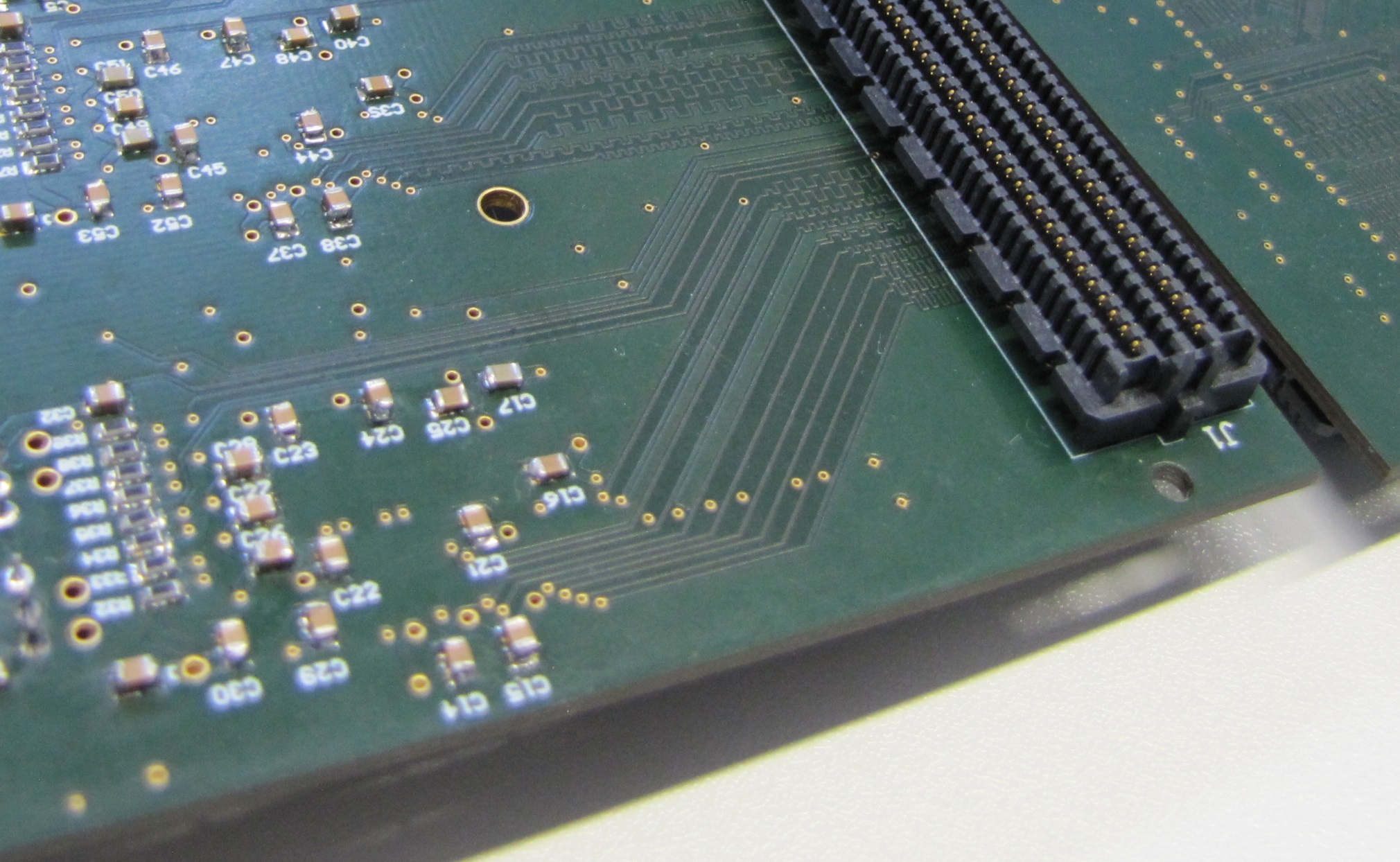
3. What’s the difference between Molex and Samtec FMC connectors?
Molex and Samtec FMC connectors are intermateable and interchangeable. A product intermateability specification is available from Molex here and from Samtec here. However, the FMC connectors for mezzanine card side differ in their appearance. The picture below shows Molex FMC connectors and Samtec FMC connectors. We have received the FMC connectors as free samples from Molex and Samtec.

4. What EEPROM can be used for FRU information storage?
In general, any serial EEPROM with I2C interface can be used. It should be at least 256 bytes in size. The most significant bits of the 7-bit I2C address must be 0b1010xxx, where the two least significant bits are determined by the GA[1:0] pins of the FMC connector.
GA[0] is connected to address bit[1] and GA[1] is connected to address bit[0]. Address bit [2] of the 7-bit address[6:0] indicates the addressing width.
EEPROMs with a size of 256 Bytes or lower use one-byte addresses, which should be masked with a low address-bit[2]. Larger EEPROMS use two-byte addresses, which is masked with a high address-bit[2].
For example, the address 0b1010001 can be used for an EEPROM with 256 Bytes (GA[1:0] = 0b10). The address 0b1010101 can be used accordingly for larger EEPROMs with two-byte addresses.
You can use the FMC FRU EEPROM Programmer to verify and configure an I2C EEPROM.
Here is a list of commonly used memory chips we have seen on several FMC modules.
| Manufacturer | Part number | Description | Memory size |
|---|---|---|---|
| Microchip | AT24C02D | 2k I2C Serial EEPROM | 256 x 8bit |
| STMicroelectronics | M24C02 | 2k I2C Serial EEPROM | 256 x 8bit |
| Microchip | 24AA64 | 64k I2C Serial EEPROM | 8K x 8bit |
| Microchip | 24LC64 | 64k I2C Serial EEPROM | 8K x 8bit |
| Microchip | AT24C256C | 256k I2C Serial EEPROM | 32K x 8bit |
| On Semiconductor | CAT24C256 | 256k I2C Serial EEPROM | 32K x 8bit |
| Microchip | AT24C512C | 512k I2C Serial EEPROM | 64K x 8bit |
5. What is the pinout of the FMC connector?
The FMC connector Pin Assignments are described here.